
Posted on February 4, 2003
Introduction
|
This article describes a Mini-ITX system designed and built for "Devilcat", a
homemade mobile robot. To give readers some idea of what I was working with, Devilcat's skeleton is approx. 15" diameter. The whole robot weighs approx. 40 lbs, and is powered by 2 x 12v/12Ah sealed lead acid batteries. It was designed to carry a "real" computer system, (e.g. COTS x86) but even so, there is little room for wasted power and space.
The criteria I established for a computer:
1. Fit on the robot's 9"x11" top deck.
2. Draw less than 30 watts. less is better.
3. Have both a parallel port and a serial port.
4. Support an 802.11b interface of some sort.
Items 1 and 2 are self explanatory. A parallel port is required because that is how the robot's drive and sensor electronics are interfaced. The serial port is needed for use as a terminal when necessary for debugging purposes. The wireless network card is used for routine control, programming, and telemetry.
ATX motherboards are too big and draw too much power. Industrial grade embedded systems are small and low power, but are usually expensive, underpowered, or both. Mini-ITX systems, however, are right on the mark.
I chose the EPIA 5000 because it's the board with the lowest power consumption. According to VIA's documentation, it draws only 10W while idle, and never more than 15W. This a very reasonable load for a 288 watt-hour battery bank. The Mini-ITX form factor is small enough.
System Configuration
Mainboard/CPU: VIA EPIA 5000 / VIA Eden 533MHz
Memory: 64MB PC100 SDRAM (to be upgraded soon)
Hard Disk: Seagate 2.0 GB IDE
Network: Netgear MA-311 802.11b interface
Power Supply: Custom
Installation
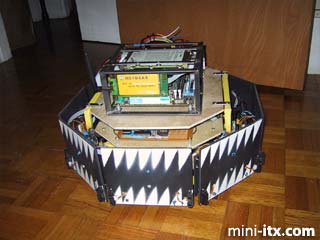
Due to the fact that Devilcat's upper deck is above its bump sensor ring, some sturdy impact protection was in order. For this an 8"x8"x4" box welded out of 1/2"x1/8" steel was chosen. The motherboard is mounted on standoffs above the bottom of the box and the hard disk hangs under the top. There is enough clearance for DIMMs underneath the disk, and the 802.11 NIC is off to the side, but still within the frame. The whole assembly was then screwed down to the front end of the wooden top deck, leaving room behind it for the PSU.
The PSU
I was unable to find much in the area of 24v input ATX power supplies. There are several companies selling 24v input supplies that are the general size, shape, and power rating of desktop ATX supplies, but these are far to large for my application. There are a few 12v supplies, but they're expensive and because Devilcat's batteries are wired in series for 24v, I would still have to use a 24v->12v converter. Thus, I designed and built my own "ATX" power supply. The 5VSB rail comes from a National Semiconductor LM2574 and is rated for 500mA. The 12v rail comes from an LM2576, and is rated for 3A, though without a heatsink it cannot handle that continuously. (That was intentional - it does not use anywhere near 3A@12V continuously, but a 500mA chip was not able to spin up a hard disk.) The 5V and 3.3V rails, from which most of the power is drawn, are connected to a matching pair of homemade mosfet buck-sync converters. The whole PSU is connected to a 2.5A circuit breaker. While idle, the system draws about 650mA from the (24v nominal) main batteries.
Pictures
|
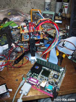
The system runs for the first time off the custom power supply.
|
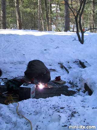
Case construction in progress.
 |
 |
 |
Quick Links
Mailing Lists:
Mini-ITX Store
Projects:
Show Random
Accordion-ITX
Aircraft Carrier
Ambulator 1
AMD Case
Ammo Box
Ammo Tux
AmmoLAN
amPC
Animal SNES
Atari 800 ITX
Attache Server
Aunt Hagar's Mini-ITX
Bantam PC
BBC ITX B
Bender PC
Biscuit Tin PC
Blue Plate
BlueBox
BMW PC
Borg Appliance
Briefcase PC
Bubbacomp
C1541 Disk Drive
C64 @ 933MHz
CardboardCube
CAUV 2008
CBM ITX-64
Coelacanth-PC
Cool Cube
Deco Box
Devilcat
DOS Head Unit
Dreamcast PC
E.T.PC
Eden VAX
EdenStation IPX
Encyclomedia
Falcon-ITX
Florian
Frame
FS-RouterSwitch
G4 Cube PC
GasCan PC
Gingerbread
Gramaphone-ITX-HD
GTA-PC
Guitar PC
Guitar Workstation
Gumball PC
Hirschmann
HTPC
HTPC2
Humidor 64
Humidor CL
Humidor II
Humidor M
Humidor PC
Humidor V
I.C.E. Unit
i64XBOX
i-EPIA
iGrill
ITX Helmet
ITX TV
ITX-Laptop
Jeannie
Jukebox ITX
KiSA 444
K'nex ITX
Leela PC
Lego 0933 PC
Legobox
Log Cabin PC
Lunchbox PC
Mac-ITX
Manga Doll
Mantle Radio
Mediabox
Mega-ITX
Micro TV
Mini Falcon
Mini Mesh Box
Mini-Cluster
Mobile-BlackBox
Moo Cow Moo
Mr OMNI
NAS4Free
NESPC
OpenELEC
Osh Kosh
Pet ITX
Pictureframe PC
Playstation 2 PC
Playstation PC
Project NFF
PSU PC
Quiet Cubid
R2D2PC
Racing The Light
RadioSphere
Restomod TV
Robotica 2003
Rundfunker
SaturnPC
S-CUBE
SEGA-ITX
SpaceCase
SpacePanel
Spartan Bluebird
Spider Case
Supra-Server
Teddybear
Telefunken 2003
TERA-ITX
The Clock
ToAsTOr
Tortoise Beetle
Tux Server
Underwood No.5
Waffle Iron PC
Windows XP Box
Wraith SE/30
XBMC-ION