Board Connectors, Headers
& Jumpers
As with previous EPIAs, VIA have managed to
pack a lot of connectors and headers into a small space. The
EPIA Ms have the following connectors:
2 x IDE Hard Disk connectors,
both supporting Ultra DMA 33/66/100/133. Up to 4 hard drives,
optical drives or other IDE devices can be connected (2 per
channel, configured as a Master and a Slave drive)
Case Connectors
- somewhere to plug your Power and Reset switches, LEDs for
Power, Hard Disk activity and Sleep mode (when the
power is on but the machine is suspended), and a case speaker.
Fast IrDA Infrared Module
Connector (FIR). We would recommend a USB-based ATI
Remote Wonder to solve your remote control needs - it also
works round corners...
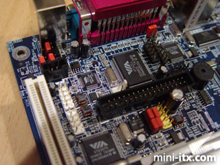
PS2 Header (called
the Consumer Infrared connector/CIR header on the classic
EPIAs). This is the block of 4 red jumpers in the picture,
which connect the mouse and keyboard sockets to the VT1211
Super I/O chip on the motherboard. By removing these jumpers
you could bypass these sockets and connect a custom input
device directly to the motherboard. Don't forget the pins
are at a 2mm pitch and pullup resistors are needed between
the +5v and the four data pins - 10kOhm should do it.
USB 2.0 header,
to attach 2 additional USB 2.0 ports. This is the yellow header
in the picture. The provided USB 2.0 and Firewire module (2
of each) plugs into this, or you could use the connector on
your EPIA M compatible case. This is an improvement over the
previous EPIAs, which have a non-standard USB 1.1 pin-header.
Wake-On LAN connector
- attaching this to a WOL compatible network card allows the
system to be powered up when a signal is received through
the card. On the classic EPIAs this is called Wake-On Modem
and doesn't have the natty plastic housing the EPIA M has.
There are no physical Firewire (IEEE1394)
connectors on the board, but 2 can be added using the twin
Firewire headers. The provided
USB 2.0 / Firewire module attaches to this, colour coded again
to minimise explosions. They're the two white headers on the
left of the picture - classic EPIAs don't have Firewire capabilities.
The EPIA M has a second serial port in header
form, COM2. Useful for any number of serial applications without
tieing up the external COM1 port. Another feature missing
from the classic EPIAs.
Chassis Intrusion Detector
- when we see a case with a chassis intrusion sensor, we'll
tell you what this does. You probably know anyway. It's the
two white pins in the middle of the picture.
Floppy Disk Drive Connector
- for connecting 360K (!) to 2.88M floppy drives - thankfully
not present on the classic EPIAs. Here at Mini-ITX we don't
really see the point in floppy drives any more. The sooner
they are eradicated from the world, the better. We've got
the internet, CDRs are ten a penny and hold a bazillion times
as much information, and we can even emulate a floppy over
a LAN using PXE. It's the evil looking black mass in the middle
of the picture, but don't look at it directly - it'll put
a hex on you.
CD-In Connector.
Another connector that used non-standard pin spacing on the
classic EPIAs, but in EPIA M format uses standard spacing.
An appropriate audio lead would usually come with your CD
or DVD drive.
I2C Connector.
A Small Area Network (SAN) is used to connect the Integrated
Circuit (IC) components on a circuit board, or within a box
or system. Components can be the PC, a keypad, LCD display,
status indicators or switches and sensors. I2C
is one such system - it's an Inter-Integrated Circuit Bus
(geddit?). The classic EPIAs don't have this. Pretty useful
if you're making a robot.
Front Audio Connector
- working much like the PS2 header, the rear audio connectors
can be disabled and routed to a front panel for convenient
connection and control of audio devices. The black header
at the top left of the picture.
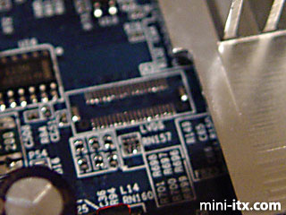
Gaping hole for an optional LVDS
Module Connector. Low Voltage Differential Signaling is a
low power method for high-speed (gigabits per second) data
transmission. LVDS is interesting because it uses 3 voltage
levels instead of the usual binary method to encode data.
at a higher maximum transfer rate. Used extensively in laptops
as a flat panel display interface. Unfortunately, we've never
seen an LVDS Module equipped EPIA M in retail, and unless
someone makes one, that old VAIO can breathe easy. Super-small
10x5mm connector with 40 pins - not present on the classic
EPIAs, but they have the equally unused Video In Connector
and PCI Riser Card Connector instead.
There are two jumpers on the motherboard.
The first clears the CMOS RAM, useful for clearing your BIOS
settings after a disastrous RAM tweaking attempt. Only do
this when the system is off. The second selects between RCA
Video or S/PDIF output on the dual-purpose Video/Audio rear
connector. It's the single red jumper, and starts life in
the RCA position. Can anyone spot the deliberate mistake in
the EPIA M manual?
The classic EPIAs have several more jumpers
than the EPIA Ms, for selecting the FSB of the motherboard,
enabling auto rebooting after power failure, enable/disabling
CPU Strapping, and enable/disabling the Disk on Chip BIOS
that 99.9% of them don't have anyway.
All EPIAs have ONE PCI
Slot. Choose your card wisely. This isn't as bad as
it sounds - USB sockets can be turned into second and third
ethernet interfaces with appropriate adapters, and there is
already on-board audio and a whole slew of standard interfaces.
Probably the best use of the slot would be with a PVR card,
or a decent 3D card (or a card supporting both functions).
A two slot right-angled riser card is available, but no mainstream
cases currently support it.
Fan Noise
and Cooling -->